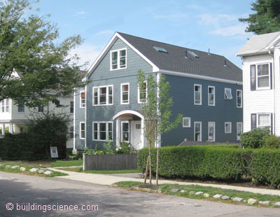
September 2010 saw the completion of the second project participating in National Grid’s Deep Energy Retrofit (DER) pilot program. This program provides financial incentives and technical support to residential retrofit projects that commit to achieving significant energy reduction. As the Technical Team in this pilot program, Building Science Corporation (BSC) supports the projects by evaluating and approving project plans, providing technical support, and performing site visits for verification of measures and testing. BSC also supports the program by participating in DER workshops.
This project involved an extensive interior and exterior renovation of an uninsulated two-family home built in 1925. The work involved for this retrofit was significant, but it restored the original charm of the interior and exterior of the residence while at the same time dramatically reducing energy demands. Energy-saving improvements for the project included a super-insulated enclosure, high performance windows, high efficiency heating and cooling, solar water heating, and mechanical ventilation. With support from the National Grid DER program, insulation levels were increased and the project was improved in many details with rigorous peer-review and supervision.
The renovation plan included a conditioned shared basement, a finished third floor to be part of the upper unit, and upgrades throughout both units.
Project Team: Byggmeister, Inc., General Contractor; The DEAP Energy Group, DER Design Consultant; Building Science Corporation; National Grid, Massachusetts
Location: Belmont, Massachusetts
Description: Comprehensive renovation of circa 1925 two-family residence; 4,090 ft2 above-grade living space, 3-story residence with conditioned basement.
Completion Date: September 2010
Estimated Annual Energy Savings: Projected 74% energy use reduction compared to the pre-retrofit residence; with the addition of PVs, expected to meet Thousand Home Challenge
Design
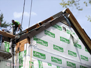
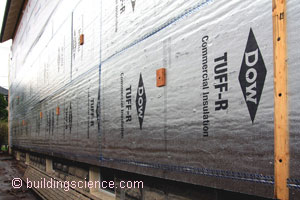
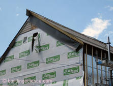
The overall retrofit strategy for the enclosure for this project was to literally wrap the above-grade portion of the house in a continuous and sealed layer of insulation. As part of the National Grid DER pilot project, the goals for the thermal performance of the enclosure were R-40 for the exterior walls and R-60 for the roof. These targets were met by covering the existing board sheathing of the walls and roof with multiple layers of foil-faced polyisocyanurate insulating sheathing and by blowing cellulose insulation into the previously uninsulated wall and rafter bays. To accommodate the wrapping of the insulation from the wall to the roof, the existing rafter tails were sawed off. New eave and rake overhangs were built and attached to the building structure through the insulating sheathing. All windows were replaced with triple glazed windows located in the outer plane of the retrofit wall assembly.
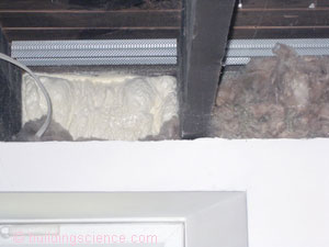
With exposed stone foundation walls, the existing basement was cold, damp, and was subject to minor flooding. A sub-slab interior perimeter drainage system connected to a sump pump was installed for water management. Since the basement was to contain mechanical equipment and some finished space, it was included within the thermal enclosure. Closed-cell high-density spray foam insulation was applied to the interior side of the foundation walls and covered by a steel stud framed partition wall with mineral wool insulation.
The existing oil boiler steam heat system was replaced with a new energy efficient forced air system with heating and cooling. The decision to change to forced air required installation of ductwork for air distribution. This was not a major obstacle since much of the interior was being opened up for renovation. Also, as a two-family building, ductwork for the lower unit could be primarily in the basement while ductwork for the upper unit could be added as the attic was being finished.
The air sealing target for National Grid DER projects is 0.1 cfm at 50 Pascals (cfm50) per ft2 of enclosure which corresponds to 750 cfm50 for this project. As a result of installing a continuous air barrier system over the outside of the building and carefully detailing the air sealing of all penetrations, seams, edges and joints, the final blower door test measured air leakage of 590 cfm50, exceeding the target by 20%.
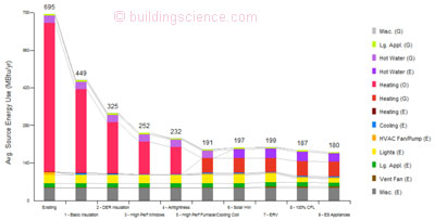
Image from BSC generated by NREL’s BEOpt 1.0 for retrofits
Enclosure Design
Roof Assembly: Compact (unvented) roof assembly with existing 7” deep rafter bays filled with netted cellulose insulation and with three 2” layers of foil-faced polyisocyanurate exterior insulating sheathing.
Wall Assembly: Existing wall framing cavities filled with dry cellulose and two 2” layers of foil-faced polyisocyanurate exterior insulating sheathing.
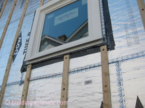
Window Specifications: New Paradigm triple-glazed, krypton/argon blend, low-E vinyl windows; U=0.2, SHGC=0.25.
Infiltration: Self-adhering membrane over existing roof sheathing provides air control in field of roof. The taped outer layer of insulating sheathing on the wall is the air control layer for the field of the walls. The roofing membrane overlaps the exterior wall insulation to provide a continuous transition. Closed-cell spray foam provides the air control layer for the foundation wall. The transition from the exterior wall air control to the foundation wall air control is through the mudsill with sealant applied between the exterior insulating sheathing and the mudsill and the spray foam over the foundation wall extending up over the mudsill.
Foundation Assembly: Conditioned basement with 3” closed-cell, high-density SPF insulation applied directly to stone foundation walls covered by metal stud walls with rock wool insulation. Sub-slab perimeter drainage system was installed and connected to a new sump pump. A drainage mat was installed along the base of the foundation wall and down under the new section of slab to allow foundation walls to drain to the sub-slab system.
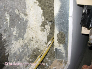
Closed-cell spray foam with rock wool insulation
Construction
The builder and homeowner acknowledged the importance of air leakage control for a successful deep energy retrofit by including an airtightness goal in their contract. It would do well for other projects to follow this example.
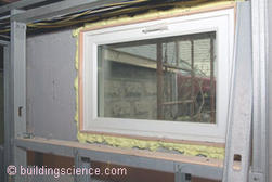
The enclosure design established the air control layer at the roof to be the membrane applied over the existing sheathing (and under the exterior insulation) whereas at the walls, it shifted to the outer layer of exterior insulating sheathing. While transitioning the air barrier from the roof to the walls was fairly straightforward in spite of the change in location of plane, details for the transition at the walls to the windows and to the mudsill at the basement was complicated by this choice. To make these transitions simpler, BSC had recommended moving the wall air control layer to the housewrap layer over the existing sheathing. However, the contractor was able to implement effective transition methods as confirmed by the final blower door test.
Mechanical Design
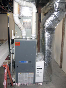
Heating and Cooling: For each unit, 96.7 AFUE sealed combustion natural gas furnace in conditioned space with AHRI-rated 14 SEER/12 EER coil installed and connected to outdoor AC unit.
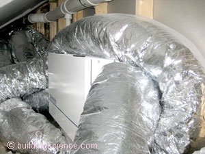
Ventilation: For each unit, Energy Recovery Ventilator installed with dedicated ductwork; outside supply ducted to common space; inside exhaust taken from bathrooms.
Space Conditioning Distribution: Entire distribution system within thermal enclosure: ductwork in basement for lower unit; ductwork in attic kneewall space and floors for upper unit.
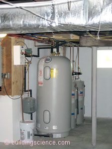
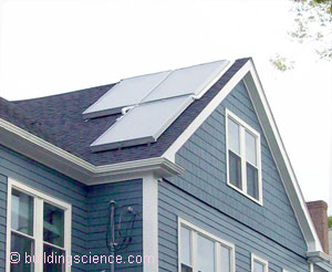
DHW: Solar thermal with common 100 gal. tank and, for each unit, a 40 gal. electric backup tank.
Lighting: ENERGY STAR® CFL lighting.
Appliances: ENERGY STAR® dishwasher, refrigerator and clothes washer.
Site Generated Power: 4.3 kW PV system
Testing
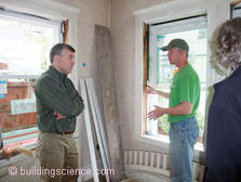
During the project, BSC visited the site to observe the implementation of the different measures included as incentives in the project. This included inspection of installed window details and of insulation before the exterior and interior finishes were applied.
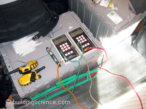
After the renovation was substantially complete, BSC measured ventilation rates within the individual units and conducted guarded blower door testing to determine the overall air tightness of the building. The blower door test result of 590 cfm at 50 Pascals (cfm50) was a dramatic improvement over the pre-retrofit air blower door test result of 5700 cfm 50. 590 cfm50 corresponds to 0.08 cfm50 per ft2 of enclosure which exceeds both BSC’s Building America target of 0.25 cfm50 per ft2 and the National Grid DER Pilot target of 0.1 cfm50 per ft2.
Moving Forward
The DEAP Energy Group is continuing to commission and monitor the operating conditions of the project now that the residence is occupied. In addition, agreements between National Grid and the homeowners stipulate that the homeowners will make energy consumption data available for review and analysis for a period including at least two full heating seasons after completion of the project. This, along with feedback from the occupants, will provide valuable information to assist with future DER projects.
Design Challenge: When the Basement Slab Cannot be Insulated Insulating the basement is recognized as best practice for an energy retrofit because it reduces heat loss and eliminates basement condensation and damp air problems as well as providing dry storage space and a conditioned space for mechanical equipment. To fully accomplish these results, it is necessary to insulate the basement slab as well as the walls. For this project, applying insulation over the existing slab would have resulted in insufficient head height in the basement. An alternative solution would have been to remove the existing slab and excavate below so that a layer of insulation could be accommodated. This approach was rejected because it would have put the old foundation wall structure at risk. As a compromise that would address some of the moisture-related issues, an application of moisture control epoxy coating was applied over the slab. In addition, the basement conditions are being monitored to determine if a dehumidifier is needed there. |

