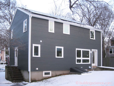
The current owner purchased this bank-owned and unoccupied home in 2010 with the intention of conducting significant energy performance improvements prior to occupancy. The National Grid Deep Energy Retrofit Pilot Program provided technical and financial assistance to extend these renovations to the level of a deep energy retrofit (DER).
The retrofit project for this home included a comprehensive enclosure retrofit and new heating, cooling and ventilation systems. Prior to the retrofit project, the home had fiberglass cavity insulation in the attic floor, exterior framed walls and between wood framing to the interior of the basement foundation walls. The home had a forced-air duct system that employed framing cavities for some of the returns.
Through grants and product donations, the owner was able to supplement the enclosure measures with advanced combination space/water heating, high efficiency heat recovery ventilation, a photovoltaic system, and energy monitoring equipment. The owner is pursuing Thousand Home Challenge designation.
This test home provides an example of a thoroughly comprehensive retrofit that did not involve major additions or changes to the configuration of the building enclosure.
Project Team: Boston Green Building, Builder and DER Lead; Building Science Corporation, DER Consultants and Technical Support; National Grid, Massachusetts, DER Pilot Program Administrator/Sponsor
Location: Milton, Massachusetts
Description: 2,368 ft2 (including conditioned basement) comprehensive renovation of circa 1960’s Garrison Colonial
Completion Date: February 2011
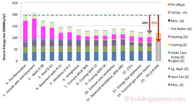
Estimated Annual Energy Savings: 39% energy use reduction before PV; 57% reduction indcluding PV contribution
Project Website: http://www.miltongreenhome.com/
Design
The design for this extensive renovation included super-insulation of the thermal enclosure and reconfiguration of the spaces within the thermal enclosure.
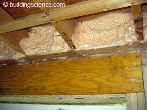
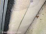
The home already had insulation between wood framing against the concrete foundation walls. However, the insulation was a fibrous insulation with an interior-side vapor barrier. This system did not provide adequate insulation or management of moisture risks. The builder specified closed-cell spray foam insulation for the retrofit of the foundation wall. The existing wood framing was incorporated in the plan and re-used, after some height adjustment, as the frame wall to support a gypsum board thermal barrier for the insulation.
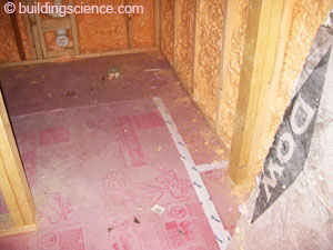
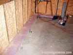
The design called for rigid XPS insulation installed directly over the concrete basement floor. The seams of the rigid insulation are taped and the perimeter is embedded in the spray foam of the wall to create a continuous airflow control for the foundation system.
The project team determined that liquid water was not an adequate risk to merit a drainage system at the basement floor. Hence, there is no drainage mat between the rigid insulation placed on top of the slab. Still, a sump pit was cut into the existing slab to provide a location where the homeowner will be able to install a sump pump to remediate liquid water problems should such be experienced at some time in the future.
The design thickens walls with a layer of exterior insulation. The existing roof plane was retained in the design as the builder opted to provide insulation to the inside of the roof sheathing.
The builder selected casement windows to replace existing double hung windows. The intention behind the selection of casement windows was to minimize air leakage through window units.
The mechanical system plan included forced-air heating and cooling distribution and balanced ventilation. The equipment selection for this system as well as the water heating system and configuration of the attic/roof insulation were dictated by the availability of donated products.
Enclosure Design
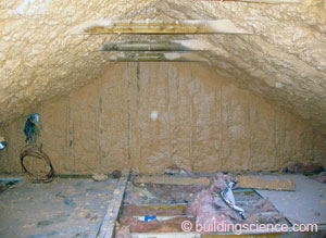
Roof Assembly: R-56 (nominal) unvented roof: New asphalt shingle roof and underlayment over existing roof sheathing; rolled fiberglass batt as eave backstop for 8” of closed-cell spray foam between and over the existing 2x6 rafters.
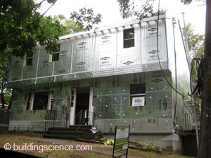
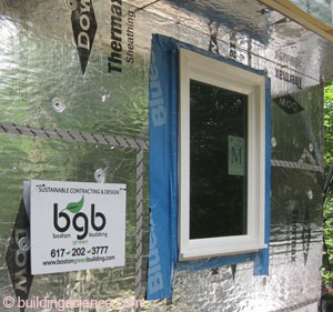
Wall Assembly: R-38 (nominal): Fiber cement cladding installed over 1x3 wood furring strips; two layers of 2” polyisocyanurate exterior insulating sheathing; joints of foil-faced outer layer offset and taped; housewrap with joints lapped and seams taped applied over existing wall sheathing; existing 2x4 wall cavities with cellulose or existing fiberglass insulation.
Window Specifications: New EcoShield triple pane, low-E, argon fill, vinyl framed casement windows; U=0.21, SHGC=0.18; window installed proud of drainage plane on strapping.
Air Sealing: Housewrap with joints lapped and seams taped under the taped outer layer of insulating sheathing on the wall is the air control layer for the field of the walls; closed-cell spray foam provides the air control layer for the foundation wall; the transition from the exterior wall air control to the foundation wall air control is through the top of the foundation wall and mudsill relying on a tight joint between the exterior sheathing and the mudsill and then the spray foam over the foundation wall extending up over the mudsill.
Foundation Assembly: Conditioned basement with closed-cell spray foam applied to existing foundation walls and partially embedding repositioned wood frame wall; 2” XPS rigid insulation with joints taped and perimeter embedded in wall spray foam over existing slab under floating floor; new sump pit added.
Construction
During construction, the availability of donations changed a few specific aspects of the plan. The project team was able to adapt to these changes although the initial design of the project may have been slightly different had the availability of the products and equipment been known prior to construction.
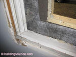
The builder installed the house wrap and exterior wall insulation before installing the new windows in the existing openings. This sequence complicates the transition of the house wrap airflow control at the window. In this project, the exterior face of insulating sheathing was also detailed as an airflow control layer and may have had a more dominant airflow control role.
To protect the basement slab insulation from construction abuse, the builder installed just a 1’ wide strip of insulation around the perimeter before re-installation of the wood stud wall and application of spray foam at the foundation wall. This allowed for a continuous thermal and capillary break beneath the wood framing. The sequence also allowed the spray foam contractor to embed the floor insulation perimeter in spray foam for transition of airflow control. When the rest of the basement slab insulation was installed, it was a simple matter to seal it to the perimeter starter strip.
Mechanical Design
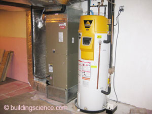
Heating and Cooling: Hydro-air heating with heating supplied by A.O. Smith Vertex™ high efficiency direct-fired storage water heater; central cooling with with 16 SEER/13.1 EER 2.5 ton AC.
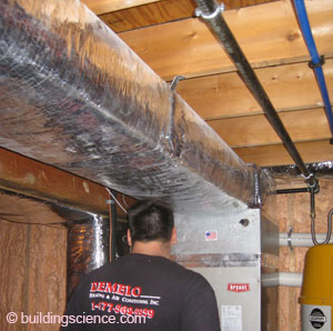
Ventilation: Venmar EKO 1.5 HRV system ducted to heating/cooling distribution system.
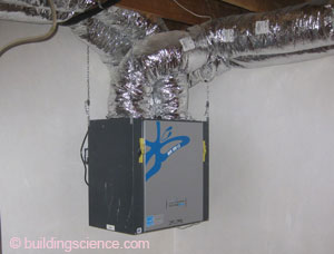
Heat recovery ventilator (HRV)
Space Conditioning Distribution: Entire distribution system within thermal enclosure.
DHW: A.O. Smith Vertex™ high efficiency direct-fired storage water heater.
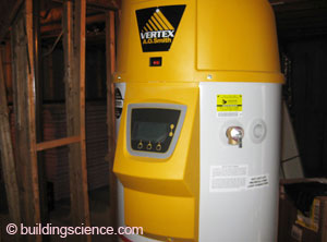
Direct-fired storage water heater
Lighting: ENERGY STAR® CFL lighting.
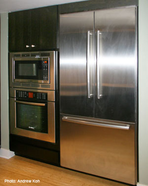
Appliances: ENERGY STAR® dishwasher, refrigerator and clothes washer.
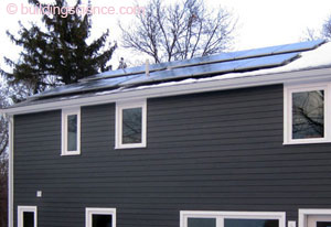
Site Generated Power: 2.8 kW PV array.
Testing and On-Site Technical Support
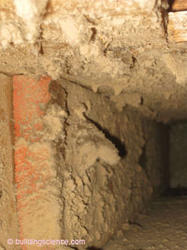
Observations of framing cavity returns that BSC made during a preconstruction site visit provided the motivation to entirely replace the existing duct system.
During the course of construction BSC conducted multiple site visits to review construction details with the general contractor. BSC advised of the need to tape the top edge of membrane flashings and also pointed out the complication to airflow and water control caused by installing windows over strapping instead of in plane with the drainage plane.
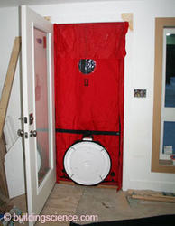
BSC performed both pre- and post-retrofit air leakage testing to assess the air leakage reduction. The pre-retrofit air leakage measurement was actually quite good for an existing home of this age at 1695 cfm at 50 Pascals or near 4 ACH50. BSC measured the post-retrofit air leakage to be 584 cfm50 or 1.6 ACH50.
Moving Forward
The homeowner commissioned extensive energy monitoring systems in order to guide the family toward meeting the ambitious Thousand Home Challenge goals for the home. The energy monitoring provides a unique opportunity to gauge the performance of the enclosure retrofit, mechanical system and site generation strategies. The homeowner’s commitment to share data with BSC and the DER Pilot Program sponsor provides further opportunity to learn from this project.
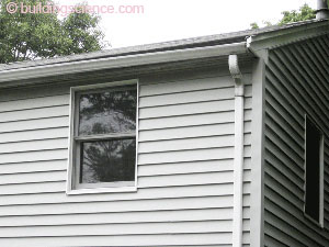
Design Challenge: Retrofit Roof Strategy For various reasons, the builder included a vented roof with air sealing and insulation at the attic floor in the DER design. To accommodate the additional wall thickness of 4” exterior foam and furring strips, the roof eaves were extended. Then, the roof was re-shingled. As is shown in the photograph of pre-retrofit conditions, the second floor window heads were already very close to the eave soffit (and the gable end overhangs were weak). Extending the eave overhang along the slope of the existing roof meant that the window heads actually had to be lowered to allow for some window trim above the second floor windows. Later in the project, when the homeowner decided to pursue an unvented roof with the attic inside the conditioned space, the only practical option was closed-cell spray foam installed to the underside of the roof deck In retrospect, the design decision not to insulate over the roof represents a missed opportunity: exterior insulation and overclad in combination with a “chainsaw” approach would allow the soffit to stay at same height as existing or even go higher. An exterior insulation and overclad approach would also have allowed more insulation over the top plate of the wall and a more robust air flow control transition than is possible with the approach implemented. |

