Airtightness testing has long—since the 1980’s—been used to test high-performance housing. The 2012 version of the International Residential Code requires testing of every new home. Recently there has been a growing trend of testing the airtightness of large buildings as well. This digest reviews why one would invest in airtightness testing for a large building, how the testing is done, how the results are interpreted, and how this information can be used.
Why Test?
In general, there are several reasons why information about airtightness—especially quantitative information—is useful:
- Air leaking out of the enclosure causes energy to be consumed when replacement air is conditioned. With information from an airtightness test you can estimate how much air will leak in cold weather versus warm weather, or how much more windy weather will cause a building to leak relative to calm weather. The resulting energy impact can then be estimated for any combination of weather conditions and can inform equipment sizing calculations and computer model predictions of operating energy consumption.
- You might be able to identify the existence of specific large holes that you didn’t know about. An airtightness test can’t show where your leaks are, but it will sometimes show that your building is much leakier than expected. In that case, there could be a large hole or two that accounts for a lot of that air leakage. Experienced air leakage consultants can often track down significant leakage paths using infra-red cameras and theatrical smoke during an airtightness test.
- Air leaking through the building enclosure feeds condensation—condensation that is hidden within assemblies and causes performance problems. Although condensation is only partly related to how much air passes through an assembly, it is an important factor that's useful to understand.
- Air leakage can bring polluted outdoor air into a building from, for example, a parking garage, a dumpster, or an exhaust vent. Knowing how much air goes through your building enclosure will help identify how much risk there is of bringing in outdoor pollutants. Once you know, you can set targets to minimize the risk.
The energy cost of air leakage is the least-studied aspect of airtightness in larger buildings. It is sometimes assumed that larger buildings, especially commercial buildings, are usually already sufficiently airtight that improvements would yield little benefit. However, the limited data that exists does not support this assumption. For example, Emmerich, McDowell and Anis (2005) used a building energy simulation program to predict potential annual heating and energy cost savings of 2% to 36%, with the largest savings occurring in heating-dominated climates in office and retail buildings (compared to a four-story multi-unit residential building). In climates with humid summers, air leakage can add a very significant latent load to the air conditioning equipment, both increasing energy use and resulting in less comfortable interior conditions.
Given the potential for energy savings, improved understanding of HVAC equipment loads and the management of IAQ and condensation risks, it makes increasing sense to test buildings of all sizes for airtightness and to take steps to address any air leakage.
Airtightness Testing 101
An airtightness test is a whole building test that measures how easy it is for air to leak through a building's enclosure or “skin.” One common method is to use a large fan or “blower” to extract air from or supply air to the building (see Figure 1). This fan is inserted in an airtight shroud installed in an exterior door opening. This is why, in residential construction, airtightness tests are often called “blower door tests”. The test equipment measures the airflow (how much air is moved into or out of the building) and the corresponding pressure difference acting across the building enclosure.
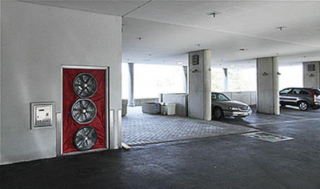
Figure 1: A “blower door” installation—computer-controlled fans are installed in special shrouds that expand to fit into a door opening.
For larger buildings, that is, with a floor area of over about 10, 000 ft2 (929m2), this test method usually requires numerous co-ordinated blower doors running at the same time. In some cases, large mobile fans requiring trailers and external power sources have been used. In all cases, large or small, a building must be prepared for testing beforehand by blocking intentional openings such as HVAC intake and exhaust grills, kitchen and bathroom exhaust fans, relief dampers, etc. (Figure 2). Sealing intentional openings is usually the part of the testing that takes the most time and effort.
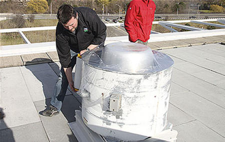
Figure 2: Sealing an intentional opening on the roof of a building during test set-up.
The results of an airtightness test in raw form are the pressure difference across the enclosure, the total airflow, and the airflow direction (in or out). During testing, numerous (typically 5 to 10) airflow measurements are collected using a range of pressure differences and flow directions. This data is then plotted to quantify the relationship between airflow and pressure difference (see Figure 3).
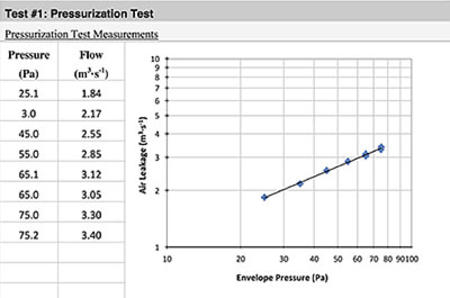
Figure 3: Example of initial pressurization test results.
Experience has shown that the results tend to form a curve, and hence it is common to plot the data in logarithmic format to mathematically force the results into a straight line. The data can be presented to knowledgeable users in that format; however, it is very useful and convenient to report the flow at a single pressure from the curve and report that number. In commercial construction, the single test pressure used for reporting is almost always 75 Pascals whereas for residential construction a pressure of 50 Pa is standard. Imperial units for air pressure, i.e. inches of water column, are sometimes used in the US. The airflow is reported in either cubic feet per minute (cfm), liters per second (lps or L/s), cubic meters per second (m3/s) or, in Europe, m3/hour.
It makes sense that the airflow measured will increase with the size of the building. To allow for easy comparisons between different buildings, two methods are used to normalize the airflow with respect to building size:
- Divide the airflow by the volume of the building or
- Divide the airflow by the area of the building enclosure being tested.
In single family residential construction, it has been customary to normalize by building volume. The measured airflow rate at a pressure difference of 50 Pa is converted to air changes per hour (ACH). Air changes per hour is simply the volume of air leaked per hour, divided by the volume of the building. The test data is then reported as a number in “ACH@50”.
Air changes per hour is also sometimes used to report air leakage for commercial and larger-scale buildings. Due to the more variable surface-to-volume ratios of the different geometries of these buildings it is more common, and technically superior, to provide the leakage rate at a specific pressure in terms of flow per unit area; in other words, as cubic feet per minute per square foot (cfm/ft2) or litres per second per square metre (lps/m2) of building enclosure area. “Area” here means the total area of six sides of the cube, i.e, the four walls and roof and slab, so all sides that are exposed to the outdoors are part of this equation. Test results are reported in “lps/m2@75Pa” or “cfm/ft2@0.3 in wc”.
Like air changes per hour, this reporting method accounts for the size of the building and therefore allows better comparisons between buildings. This enclosure area approach to normalizing results is increasingly finding favour in the residential community as well, as it separates out the measured quality of the air barrier actually constructed from choices made during design (i.e., the surface area: volume ratio).
The test pressure used to report leakage for commercial buildings is usually 75 Pa (0.3 in wc), rather than the almost universal 50 Pa used for residential buildings. The reasons are mostly historical, but higher pressures are often preferred in all situations as the spurious effect of uncontrolled pressures during a field test (e.g. wind gusts, stack effect) have a smaller potential to cause reading errors. Higher pressures, however, result in higher flows, and hence larger equipment, so pressures of more than 75 Pa are usually reserved for testing smaller scale building components (such as windows, doors, or wall samples).
Airtightness Targets
Airtightness targets, or maximum airtightness levels, are a relatively new metric for assessing building performance. To set a target, it is critical to understand that building airtightness tests measure the air leakage through the entire building enclosure (roof, walls, slabs, windows, doors, vents, etc). Historically, airtightness was specified for commercial buildings first for building components, such as windows, curtainwalls, prefabricated walls, etc. By the late 1980’s, the Institute for Research in Construction / National Research Council of Canada (IRC/NRCC) and Canada Mortgage and Housing Corporation (CMHC) had developed recommended targets for air barrier materials (0.02 l/s/m2 @75 Pa) that subsequently became part of the 1995 Canadian National Building Code. Research into the potential for damaging cold-climate condensation (Ojanen & Kumaran 1996) led to the recommendation that the maximum leakage of building components be limited to 0.2 l/s/m2@75 Pa, and this target was enshrined in the Canada Construction Materials Center (CCMC) Technical Guide for Air Barrier Systems for Exterior Walls of Low-Rise Buildings (Di Lenardo 1996). The different target values between the material airtightness, and the air barrier system tightness had evolved to a factor of ten (i.e, 0.02 for the material, 0.20 for the air barrier assembly). This large difference was due to the effect of leaks at joints and seams that were required when one used materials to create an assembly.
It is critical to understand the laboratory tests only yield data on material and systems potential airtightness: assembling a building enclosure in the field always results in more leakage and can only be tested in the field. Lstiburek (2005) proposed that the acceptable whole building (enclosure) tightness be ten times the maximum air barrier value of 0.20, that is:
Air Barrier Material 0.02 l/(s m2) @75 Pa 0.004 cfm/ft2 @ 0.3” w.c.
Air Barrier Assembly 0.2 l/(s m2) @75 Pa 0.04 cfm/ft2 @ 0.3” w.c.
Building Enclosure 2.0 l/(s m2) @75 Pa 0.4 cfm/ft2 @ 0.3” w.c.
This proposal was quickly taken up by the building industry; in the United States the General Services Administration now requires that all new buildings meet these targets. For higher performance buildings, the U.S. Army Corps of Engineers has a target of about 0.25 cfm/ft2 at 0.3 inches of water column which works out to about 1.3 lps/m2 at 75 Pa. High performance buildings sometimes use a target of under 1 lps/m2 @ 75 Pa (which was the Canadian C-2000 building program target in the late 1990s) but that is not always easy to reach.
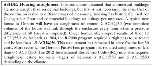
The 2 lps/m2 @ 75Pa target is not often achieved in large buildings. As recently as 2011 data from the U.S. National Institute of Standards and Technology showed an average airtightness of approximately 6.9 lps/m2 @ 75Pa for a sample of 228 commercial and institutional buildings (Emmerich and Persily 2011). This average rate of leakage is well above what would be considered “good”, and many of the buildings have poor control of airflow. An even more recent study of 16 non-residential, mostly higher performance, buildings found measured leakiness of from 0.30 to 3.80 lps/ m2 @ 75Pa (Brennan et al. 2013), exemplifying this author’s experience that very good airtightness can be achieved, but far too often is not.
A survey of the literature shows that large buildings tested by various agencies, have reported numbers that vary from as little as 0.09 to over 30 lps/m2 at 75 Pa. At the higher end of that scale, one can definitely say that your building is too leaky and its performance will suffer because of it; as you get close to 2 or 1, you know that you have a tight building. Recent experience has shown that a deliberate plan from the start of design through to early testing during construction can routinely deliver buildings with values of well under 2 lps/m2@75.
Airtightness is not just about walls, doors, and windows. In modern buildings, the air leakage through the mechanical system, grills and openings is often substantial. It is not uncommon to see half of the total leakage going through the mechanical system and that means we have to worry more about backflow dampers that actually act as backflow dampers should—that is, they should seal tight in the closed state—because this will matter to the overall tightness of the building in service. In one test, a constant pressure of -75 Pa was maintained while the coverings of the mechanical systems were systematically removed. As soon as the return air vents were opened, there was a 41% change in flow. By the time everything was opened, the flow rate was 5.46 m3/s (11575 cfm), a 67% increase from the base rate. What this tells us is that for buildings that are already quite airtight, where it would be difficult to make further improvements through changes to the enclosure, airtightness can still be improved by fixing those mechanical leaks, for example by ensuring that supply vents in the HVAC system are actually sealed during off-cycle times with better gaskets, tighter actuators, and proper damper adjustments.
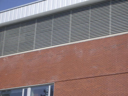
Figure 4: As vents and grilles can make up a large area on many commercial buildings,
the management of uncontrolled air leakage must also be considered.
Airtightness and Ventilation
As airtightness increases, the need for well-designed mechanical ventilation also increases. People need fresh air in their buildings, whether residential or commercial/institutional. At the same time, too much ventilation can negate the value of airtightness in terms of energy savings and, depending on the climate zone, weather conditions, and particular characteristics of the building, can also cause other problems.
In design, one should aim for almost no mechanically-induced air pressure across the enclosure. This is achieved by balancing systems so that almost the same amount of air is supplied as is exhausted. In some cases deliberate control of pressure can be used to control airflow direction—buildings that are slightly depressurised in winter will reduce their risk of air leakage condensation problems, and buildings that are slightly pressurized may have slightly more winter condensation problems (because of airflow through the remaining enclosure leaks) but will more effectively exclude pollution from, for example, a parking garage.
The term “slightly” is used in the preceding paragraph to indicate a pressure difference of only a few to 5 Pa. Pressurization, in common practise, is achieved NOT by controlling pressure, but by specifying and designing a system to supply more air than is exhausted. As modern buildings become airtight, this design methodology can result in significant problems: estimating the amount of excess airflow required to pressurize a building by only 3 or 5 Pa is practically impossible, as the required quantity of airflow is quite small. Unfortunately, by guessing at the excess airflow required, mechanical engineers often significantly over-pressurize airtight buildings, forcing air to leak out even though the building is relatively airtight. The result is the far too common scenario where a building designed and built to be very airtight, still has excessive energy loss and condensation problems because the mechanical system has been designed to force a fixed amount of excess air out of the building skin regardless of how tight. In numerous cases this has resulted in doors being blown and held open by excess pressure, whistling noises at curtainwall joints as air is forced through, and icicles forming from the façade even with very small air leaks.
The solution to the above is simply to commission the building by measuring the pressure difference caused by operating the buildings mechanical systems. This can easily be done as part of an airtightness test if the building is essentially complete, but can also be easily done after occupancy. Modifying supply, exhaust, or both flows to achieve a pressure of less than 5 Pa during low-wind, neutral temperature conditions is then usually easy to achieve (by adjusting VFD, dampers, fan motor sheaves, etc.).
It is also important to provide education to building owners so that ventilation systems are used and maintained properly after buildings are occupied. Professionals in the heating, ventilation, and air conditioning (HVAC) industry often use the motto “build airtight and ventilate right”. The “ventilate right” part should be seen as a continuous activity rather than a one-time design decision. This may require that the ventilation flows and pressure differences be measured annually, to help identify problems such as clogged filters, stuck dampers, and blocked grilles.
The Utility of Airtightness Tests
The trends are clear: the building industry will be required to meet airtightness targets, either because they are added to building codes or energy programs or because owners are looking for better buildings—buildings with less energy consumption, more comfort, better indoor air quality, and lower risk of moisture damage. One of the ways architects can use airtightness tests is to prove to the owner and code officials that the contractors and the designer together have delivered a good, airtight building enclosure. It provides quantitative verification that the methods used were successful, much like crushing a concrete cylinder shows that the required concrete strength was achieved.
Airtightness targets are useful during the design process for new buildings as well as retrofits—they establish quantitative expectations for a very important aspect of building enclosure performance and provide a key input into the mechanical designer’s load and energy calculations. Airtightness tests should therefore be an important part of the construction process—they provide confirmation that airtightness targets are met and, if timed properly, afford the opportunity to address problems before it is too late.
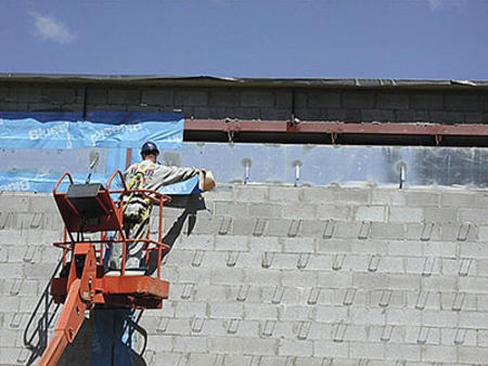
Figure 5. Achieving airtightness requires attention to detail at all transitions and penetrations from design through construction.
Airtightness testing can also be used diagnostically. For new construction, you should typically do a test as early as possible in the construction process so that if the building fails, remedial work can be undertaken to find the cause and fix it. Similarly, if you are about to do a major energy efficiency retrofit—replace windows, add insulation or take other substantive steps—it is usually advisable to do a test before you get too far into the design of the retrofit. Testing should be done as part of the assessment of the existing building, to gain an understanding of how leaky the building is, so that you can decide how much effort should be spent on airtightening versus how much effort should be spent on, for example, insulation or new windows.
By using airtightness tests regularly, architects and contractors can learn over time what works and what doesn’t and how a good tight building performs as opposed to a leaky building; they will get better and better at predicting performance and therefore be comfortable designing for more realistic airtightness performance. Furthermore, once targets are in place, and it is known that a certain target is achievable, you can then provide input to the mechanical systems designer. As we move to tighter and tighter buildings, mechanical engineers are often left guessing about what to assume in their energy calculations for air leakage, and so they tend to aim on the safe side. If you specify an air tightness target and have a method in place to test it during construction, then the mechanical engineer can do a better job of sizing the mechanical equipment for heating, cooling, and dehumidification, and also design makeup air systems to minimize pressurization. As mentioned above, a growing problem in airtight buildings is that mechanical engineers are over-pressurizing them. Just as manufacturers test the R- value of insulation so that you know what you're putting in the walls, and can design for it, measuring the airtightness of a building gives the mechanical engineer some values to use in system design.
Minimizing air leakage across the building enclosure is fundamental to high-performance buildings—that is, buildings that are low-energy, comfortable, healthy, and durable. In the end, airtightness testing is basically a quantitative quality control tool with the added benefit of making sure that you know what your mechanical system should be designed for.
References
Lux, M.W., Brown, W.C., 1986. “Air Leakage Control” in An Air Barrier for the Building Envelope. Institute for Research in Construction (IRC) Building Science Insight ’86,
Lstiburek, J. 2005. “Understanding Air Barriers”, ASHRAE Journal, Vol. 47, No. 7.
Di Lenardo, B., W. C. Brown, W. A. Dalgliesh, G. F. Poirier and M. K. Kumaran. 1995. "Air Barrier Systems for Exterior Walls of Low-Rise Buildings," CCMC Technical Guide Master Format 07195, Institute for Research in Con- struction, NRC Canada.
Ojanen, T., and Kumaran, K.. 1996. “Effect of Exfiltration on the Hygrothermal Behaviour of a Residential Wall Assembly”, Journal of Building Physics January, Vol. 19, pp. 215-227.
Emmerich SJ and Persily AK. "US Commercial Building Airtightness Requirements and Measurements." Brussels: Proceedings of the AIVC Conference, October 12-13, 2011. pp. 134 - 137. Available at http://www.nist.gov/customcf/get_pdf.cfm?pub_id=909521
Brennan T, Anis, W, Nelson G and Olson, C. “ASHRAE 1478: Measuring Airtightness of Mid- and High-Rise Non-Residential Buildings.” Clearwater, FL: Proceedings of the Thermal Performance of the Exterior Envelopes of Whole Buildings XII International Conference, December 1-5, 2013. pp 1-6.
Emmerich, S.J., McDowell, T., Anis, W. 2005. Investigation of the Impact of Commercial Building Envelope Airtightness on HVAC Energy Use. NIST Interagency Report 7238, National Institute of Standards and Technology, Gaithersburg, MD.
