Photo courtesy of the homeowner
Project Team: Synergy Companies Construction, LLC, General Contractor; Wilson Bros. Heating & Air Conditioning, Inc, HVAC Contractor; Building Science Corporation; National Grid, Massachusetts
Location: Millbury, Massachusetts
Description: Exterior-only enclosure renovation of 11/2 story single family home with 1,100 ft2 living space and conditioned basement.
Completion Date: December 2010
Estimated Annual Energy Savings: Projected 58% energy use reduction compared to the pre-retrofit residence.
Overview
This Cape Cod style house was built in 1953. While the owners had made interior improvements and necessary repairs in the 25 years since they purchased the house, they now wanted to do some exterior upgrades and at the same time tighten up the house in keeping with their long-standing goal of becoming energy efficient and reducing their impact on the environment.
This project was among the first to be accepted into the National Grid Deep Energy Retrofit (DER) Pilot program which provides financial incentives and technical support to residential retrofit projects that commit to achieving significant energy reduction. As the technical support team for the National Grid DER Pilot program, Building Science Corporation (BSC) works with the retrofit projects to ensure that their retrofit plans can meet the desired energy, durability, health and safety goals.
In order to reach the goals of a DER, the overall retrofit strategy was to apply exterior insulating sheathing to the walls and roof, replace the existing windows with high performance windows, and insulate the basement. Since nearly all of the work was exterior, the owners were able to stay in their home throughout the retrofit project.
Design
TThe overall retrofit strategy for the enclosure for this project was to first wrap the above-grade portion of the house, including the roof, with a continuous air barrier and then to wrap it again in continuous layers of insulation. Since the wall framing cavities already contained batt insulation and adding insulation to the rafter bays could easily be accomplished in the unfinished attic, the combination of exterior insulation and cavity insulation satisfied the R-40 and R-60 DER targets for the walls and roof respectively. Once the additional roof assembly was in place, eave and rake overhangs were built and attached to the building structure through the insulating sheathing. This simple action of adding overhangs results in a major improvement in water management which the original house was lacking and is a significant durability upgrade.
To complete the enclosure improvements, the windows were replaced with new triple glazed windows and the basement was insulated by applying insulation to the interior of the concrete foundation walls and over the existing basement slab.
The project replaced the existing 30+ year old oil boiler and four window air conditioners with a mini-split heat pump system to provide heating and cooling using two small ducted air handlers—one in the basement and the other in attic space—and a single outdoor heat pump condensing unit. During the winter, the owners had often preferred using their pellet stove for heating. By providing an airtight door and adding supply and exhaust ducts that connected directly to the outside, they were able to keep this and use it as a backup heating system.
As the first in their neighborhood to undergo a DER, this project serves as a demonstration for other homeowners that this type of house can be made energy efficient without making other major changes.
During the course of the project the owners decided to enlarge an existing shed dormer on the second floor which increased their 2nd floor living space. This highlights another justification for a retrofit project—use home improvement projects as an opportunity to improve energy efficiency and durability or, as in this case, vice versa.
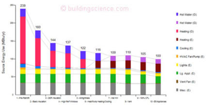
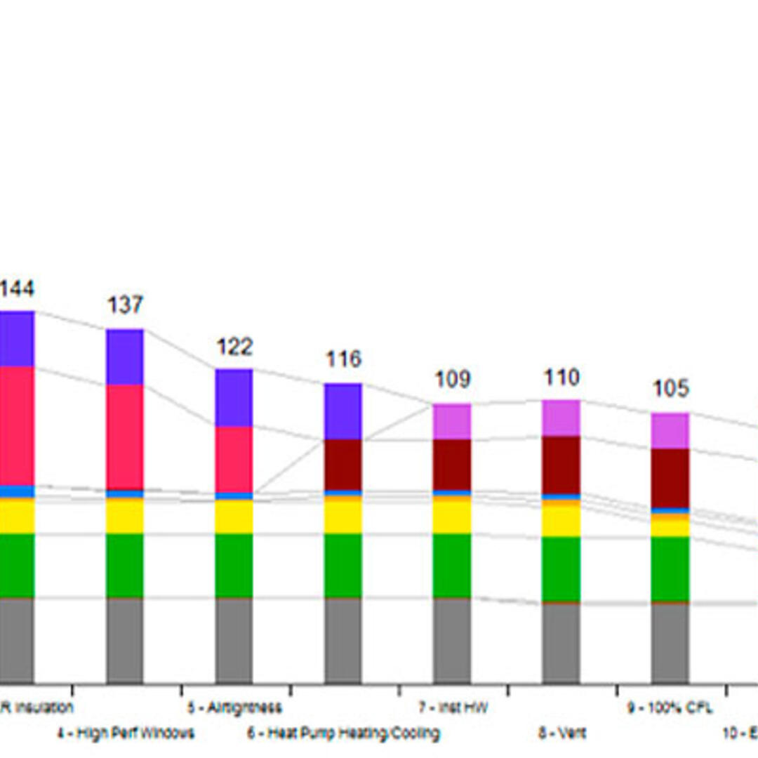
Parametric study image from BSC generated by NREL’s BEOpt 1.0 for retrofits
Enclosure Design
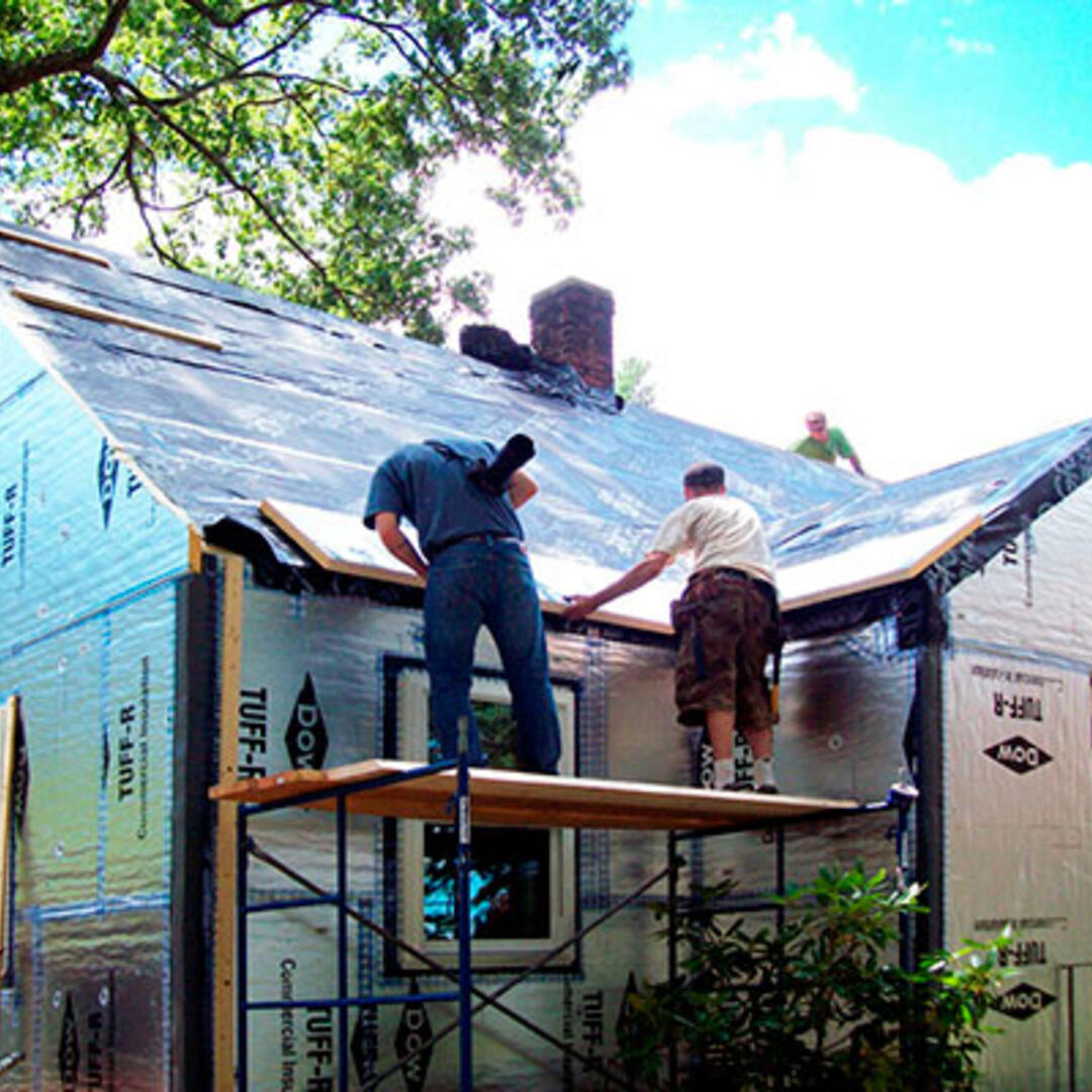
Roof Assembly: Compact (unvented) roof assembly with existing rafter bays filled with spray foam and with two 2” layers of foil-faced polyisocyanurate exterior insulating sheathing.
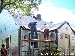
Adding insulating sheathing to roof
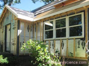
Wall Assembly: Existing wall framing cavities already contained batt insulation; two 2” layers of foil-faced polyisocyanurate exterior insulating sheathing were applied to the outside.
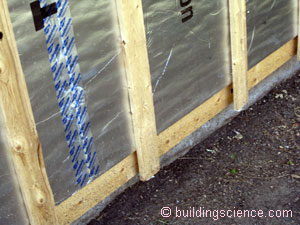
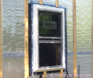
Insulating sheathing with taped joints and furring
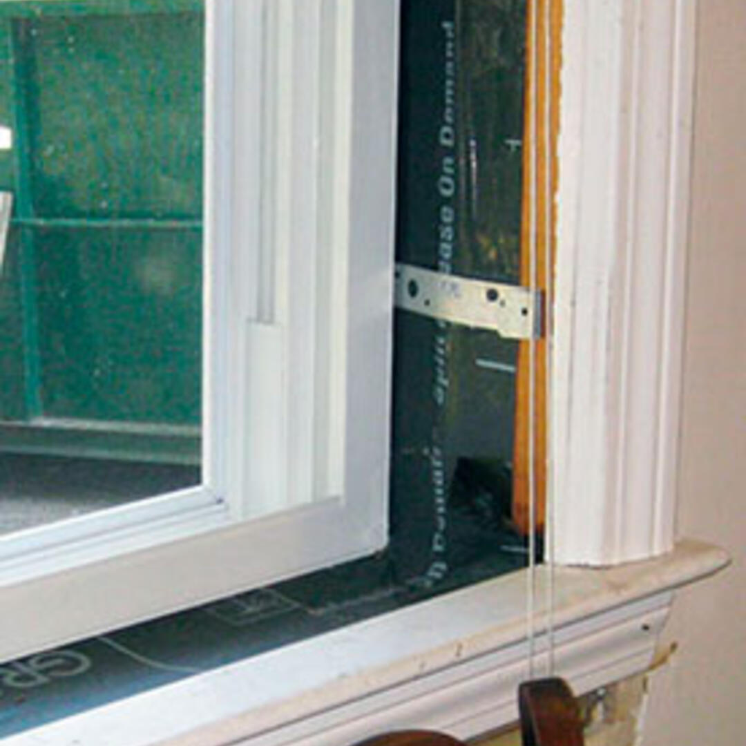
Window Specifications: New Paradigm triple glazed, argon-filled, low E double hung vinyl windows; U=0.25, SHGC=0.25.
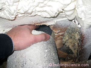
Infiltration: Self-adhering membrane over existing roof sheathing provides air control in field of roof; house wrap applied shingle style, with seams and edges taped, over the existing wall sheathing provides air control in the field of the wall; roofing membrane overlaps onto the house wrap to establish continuity of the air barrier system; air barrier system transitions through the mudsill to the spray foam insulation on the inside; this connects with the taped insulation board that is applied to the inside of the basement wall.
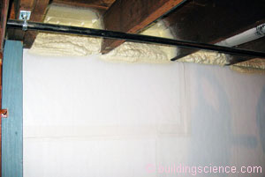
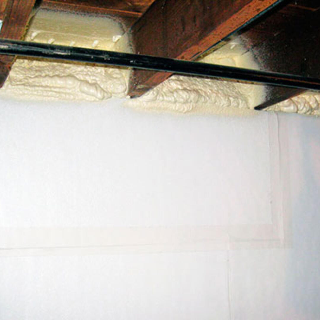
Foundation Assembly: Conditioned basement with 3” rigid polyisocyanurate insulation applied to the concrete foundation walls; to provide insulation for the concrete slab as well as provide some water management capacity, a drainage mat was placed over the existing slab, followed by polyethylene vapor barrier and then rigid insulation; a floating subfloor completes the new floor assembly.
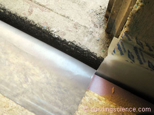
Drainage mat and polyethylene vapor barrier at slab edge
Construction
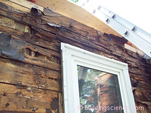
The construction process for the above grade portion of the house was fairly straightforward, especially since the contractors were experienced with applying exterior insulating sheathing in other projects. Since the existing house had no overhangs and was of a compact form, once the siding and shingles were stripped off of the board sheathing, it didn’t take long before the house looked like a box wrapped in “a blanket of insulation” as described by the owner. There was a delay, however, when some significant water damage was discovered after the siding was removed. The repairs, along with the new overhangs that provide a robust water management system, will ensure the durability of the wall structure.
For this project, the HVAC contractor was not a subcontractor to the builders but instead was contracted by the owner. This arrangement complicated the coordination effort and caused the construction phase to last longer than originally anticipated. This highlights one of the difficulties that can be experienced, especially with HVAC work, in DER projects. To attain significant energy use reduction, new design and non-standard approaches are required for the HVAC component of the project. It is best for the HVAC system designer to be an integral part of the project team from the start.
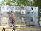
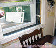

Photo (left) courtesy of the homeowner
Mechanical Design
Heating and Cooling: Mini-split heating and cooling heat pump system with two ducted air handlers and one outdoor unit; one air handler is located in the basement and one is in attic space; direct vented pellet stove is available as backup for heat.
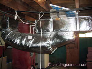
Ventilation: An outdoor air supply is integrated with each air handler; outdoor air intake ducts are provided with ventilation controllers and mechanical dampers; spot exhaust fans are provided in the bathrooms.
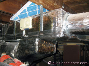
Ventilation system in basement
Space Conditioning Distribution: Insulated sheet metal trunks with insulated flex run-outs; entire distribution system within thermal enclosure; ductwork in basement ceiling for basement air handler; ductwork in attic and kneewall space and floors for attic air handler.
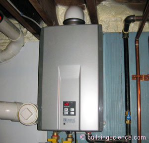
DHW: Instantaneous propane water heater.
Lighting: ENERGY STAR® CFL lighting.
Appliances: No change at this time.
Testing
During the project, BSC visited the site to observe the implementation of the measures included as National Grid incentives in the project. This included inspection of installed window details and of insulating sheathing as well as verifying that the new mechanical equipment was operational.
After the renovation was substantially complete, BSC measured ventilation rates of the individual units and conducted blower door testing to determine the overall air tightness of the building. The pre-retrofit blower door test result was 2860 CFM at 50 Pascals (cfm50). The final blower door test result was 458 cfm50. Since the 6-sided enclosure for this project was 4,278 ft2, this exceeds BSC’s 2010 Building America target of 0.25 cfm50 per ft2 but is slightly higher than the National Grid DER Pilot target of 0.1 cfm50 per ft2.
Moving Forward
There is a large existing stock of houses that are similar in age, style, and condition to the pre-retrofit version of this house. These houses have provided compact but comfortable living conditions for thousands of families and can continue to do so provided steps are taken to ensure their durability and energy use reduction. Failure to do this will likely result in teardowns replaced by new (and larger) construction with the accompanying loss of resources, embodied energy, and memories. Projects such as this demonstrate that this need not be the case.
Design Challenge: What Might Be Found Behind the Vinyl Siding As the existing vinyl siding was removed from the house, two discoveries were made. First, the vinyl siding had been applied directly over the original wood shingles. Secondly, once the old shingles and tar paper had been removed, it could be seen that there had been extensive damage to parts of the wood structure of the wall caused by water intrusion over the years. This required replacement not only of parts of the wood sheathing, but also some wall studs, parts of the mud sill and a window header. Since there was no built-out overhang on the existing house, gutters had been attached in the same plane as the wall. Any leakage or overflow of the gutters resulted in water running directly against the wall with some of it getting into the wall. Backing up of ice dams also would have contributed to the water intrusion. Given the extent of the damage, why had this not been noticed earlier? It was effectively hidden by the vinyl siding. Wood siding would have shown evidence of paint peeling or other damage, to warn of deteriorating conditions behind. The vinyl siding masks the condition of what may be behind it. Photo courtesy of the homeowner |

